
What Is a Chip Mounter? Core Function and Industrial Role
Defining the Chip Mounter in SMT Production Lines
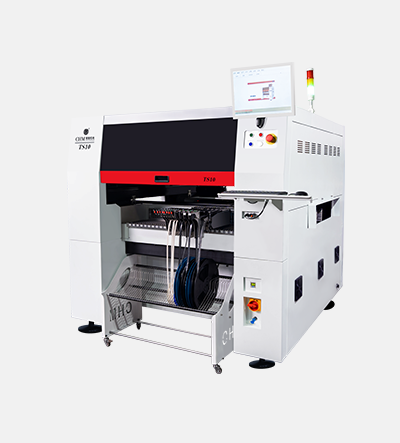
The chip mounter, often referred to as a pick-and-place machine, stands at the heart of automated Surface Mount Technology (SMT) production lines. These machines accurately place tiny electronic parts like resistors, capacitors, and those complex integrated circuits right onto printed circuit boards. Modern versions use robotic arms and smart feeding systems to position literally thousands of components each hour with incredible precision down to the micron level. What this means for manufacturers is fewer mistakes from human hands, faster production speeds, and significantly less reliance on workers for assembly tasks. Some factories report cutting their manual labor needs almost entirely, though exact numbers vary depending on the facility. With deeper integration of artificial intelligence, today's chip mounters can actually adjust themselves on the fly when components don't quite match specifications or when there are issues with the PCB layout. They're no longer just precise placement devices but becoming real brains within the manufacturing process itself.
How Chip Mounters Enable High-Density PCB Assembly
Chip mounters enable the creation of those densely packed PCBs we see in our phones, smartwatches, and all sorts of connected gadgets these days. With multi-head setups, manufacturers can work with components as tiny as 01005 size, which measures just 0.4 by 0.2 millimeters. These miniature parts allow circuit designs that would have been impossible to fit on a board not so long ago. The machines come equipped with high resolution cameras that look for reference points called fiducials. They spot any warping or shifts caused by heat changes during production, keeping placement accuracy around plus or minus 0.025 mm. This kind of precision makes it possible to stack components on top of each other and create complex connections between layers, squeezing every last bit of space out of the board without compromising how well it works. Some of the best models out there can place components at a rate exceeding 50,000 per hour. That speed matters a lot in industries like aviation and healthcare equipment manufacturing, where shrinking device size goes hand in hand with making sure everything functions exactly as intended.
Key Components of a Chip Mounter: Precision, Vision, and Control
Feeder Systems and Tape Handling for Reliable Component Supply
Feeder systems keep components flowing smoothly and properly oriented when they come from tapes, trays, or tubes. These systems have precise tape movement features working alongside smooth running guides that stop those pesky jams and misfeeds, even when dealing with tiny 0201 parts measuring just 0.02 by 0.01 inches. Getting consistent feeding right matters a lot because one good feeder can handle tens of thousands of component placements every day. If something goes wrong, the whole production line comes to a standstill. Feeders actually protect components from damage and maintain their correct position until they're picked up by the machine. This makes all the difference in maintaining production speed while still achieving high yields in large scale surface mount technology operations where downtime costs money.
Vision Alignment and Nozzle Actuation for Sub-Millimeter Accuracy
Vision systems with multiple angles and high res cameras plus built-in machine learning can hit around 0.025 mm accuracy when placing components. These systems look at those reference points called fiducials before doing any actual placement work, which helps fix issues like warped boards, rotated parts, or problems from heat changes during manufacturing. The suction nozzles on these machines change how much vacuum pressure they apply depending on what needs picking up, so delicate things like micro BGAs and those tiny pitch QFN packages don't get damaged. At the same time, laser sensors check if everything sits flat across the board surface while it's happening. All this tech working together means manufacturers can maintain really tight tolerances below a millimeter even when running hot at over 30 thousand placements per hour. And this kind of precision makes a big difference in cutting down on common assembly problems like tombstoning where components stand upright instead of sitting flat, misaligned solder joints, and those annoying bridges between pads that happen when too much solder flows.
The Chip Mounter Workflow: From Pick-and-Place to Real-Time Calibration
Step-by-Step Process: Feeding, Vision Capture, Placement, and Verification
Chip mounters execute a tightly synchronized, closed-loop workflow that ensures repeatable, high-yield placement:
- Component Feeding: Reels or trays feed parts to designated stations; vacuum nozzles retrieve components at speeds surpassing 30,000 placements/hour.
- Vision Capture: Onboard cameras inspect each component for orientation, rotation, and physical defects (e.g., bent leads or missing terminations) before placement.
- Precision Placement: The system aligns the PCB using fiducial markers, then places components onto solder paste pads with tolerances under 0.05 mm.
- Real-Time Verification: Integrated sensors validate nozzle pressure, placement angle, and positional fidelity. Deviations trigger automatic recalibration—or an immediate line stop—to prevent cascading defects.
This end-to-end automation minimizes human intervention while supporting adaptive optimization: advanced models use machine learning to refine nozzle paths, placement force, and timing based on live process data.
Selecting Your First Chip Mounter: Accuracy, Speed, and Beginner Support
Choosing your first chip mounter hinges on balancing three interdependent factors: placement accuracy, sustainable throughput, and operational accessibility.
For accuracy, prioritize machines certified to IPC-9850 standards with ±0.0001-inch (2.5 µm) placement repeatability—essential for fine-pitch components under 12 mil (0.3 mm). Speed must reflect real-world performance: evaluate verified throughput (components/hour) under typical load—not theoretical peak specs—and match it to your production volume and mix complexity.
Beginner support is equally decisive. Look for:
- Intuitive software: Graphical dashboards with real-time diagnostics and guided setup wizards
- Automated calibration: Self-correcting nozzle alignment and vision registration
- Modular training tools: Context-sensitive help, simulation modes, and progressive skill scaffolding
Long-term reliability matters most in practice. Target these benchmarks:
| Factor | Target Specification | Impact |
|---|---|---|
| Uptime | ≥98% | Minimizes unplanned production delays |
| Error Rate | <0.01% | Reduces rework, scrap, and inspection overhead |
| Maintenance | <2 hrs/month | Lowers total cost of ownership and technician burden |
Leading manufacturers now embed AI-assisted troubleshooting—cutting initial setup time by 30–50%—and emphasize repeatability within ±25 µm, ensuring stable yields as operators gain proficiency.
FAQ
What is the primary function of a chip mounter?
A chip mounter accurately places electronic components like resistors, capacitors, and integrated circuits onto printed circuit boards, mainly within automated Surface Mount Technology (SMT) production lines.
How does a chip mounter accommodate high-density PCB assembly?
Chip mounters use multi-head setups and high-resolution cameras for precise component placement, enabling densely packed PCBs suitable for compact gadgets.
What factors should be considered when selecting a chip mounter?
Consider placement accuracy, throughput speed, and operational accessibility with emphasis on intuitive software, automated calibration, and modular training tools.
How has AI enhanced the functionality of chip mounters?
AI integration allows chip mounters to adjust in real-time for mismatches in specifications or PCB layout problems, essentially turning them into pivotal systems within the manufacturing process.