
Understanding SMT Line Configuration and Core Integration Principles
The Growing Complexity of SMT Line Setup in Modern Electronics Manufacturing
Manufacturers are seeing a big change in their SMT line needs as they move towards producing many different products in smaller batches. According to recent industry data, around two thirds of electronics makers handle over fifty distinct product versions each year. The trend is pushing them to deal with tiny components such as those 01005 sized chips and BGA packages with just 0.3mm between pins, which need placement accuracy better than 25 microns. At the same time, smart connected devices bring new challenges requiring assembly lines that can handle both radio frequency parts and standard digital components together. All these factors mean that today's surface mount technology lines must be flexible enough to switch between production recipes quickly without needing someone to manually adjust everything each time there's a change.
Core Requirements for Seamless Integration of SMT Printers, Placement Machines, and Reflow Ovens
Successful SMT line integration hinges on three pillars:
- Protocol standardization: Machines supporting SECS/GEM or IPC-CFX communication reduce interface errors by 38%
- Mechanical synchronization: Conveyor height tolerances ±0.2mm prevent PCB misalignment between stages
- Thermal coherence: Reflow oven zoning must compensate for printer-induced board warpage (0.1mm/m thermal deformation)
Modular SMT Line Design: A Scalable Strategy for High-Mix Production Environments
With modular SMT setups, manufacturers can actually switch out their printer placement modules in under half an hour when they need to change products. Some interesting research into flexible manufacturing recently showed something pretty cool about these hybrid production lines. When companies mix those super fast chip shooters that hit around 50 thousand components per hour with the more precise fine pitch modules capable of 15 micrometer accuracy, they end up getting nearly 94 percent equipment usage even when dealing with all sorts of different products at once. The real advantage here is that it cuts down how much money gets tied up in expensive machinery upfront. Plus, this kind of setup works great for companies trying to keep up with constantly changing new product introductions without breaking the bank on specialized equipment every time there's a design shift.
Aligning SMT Equipment with Production Goals: Throughput, Flexibility, and Yield
Studies on line balancing show that getting printer cycle times within about 2% of placement machine speeds really helps boost production while avoiding those annoying bottlenecks that slow everything down. When it comes to making medical devices, putting together nitrogen capable reflow ovens with oxygen levels below 50ppm along with real time temperature monitoring cuts down on those pesky voiding issues by almost two thirds compared to regular air systems. And let's not forget about those flexible feeders that can handle tape reels ranging from 8mm all the way up to 88mm at the same time. These setups significantly cut down on wasted time during setup when dealing with boards that have over 300 different components.
Optimizing the Solder Paste Printing Process for Consistent SMT Quality
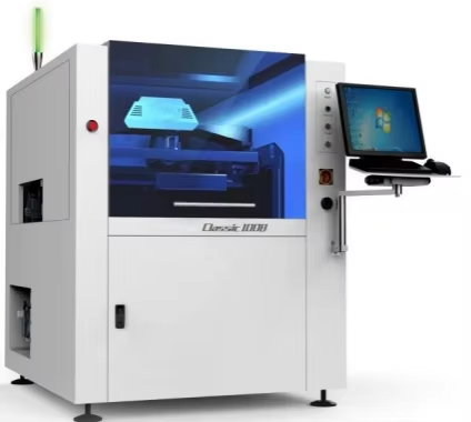
Precision Solder Paste Application Using Stencil Printers
Effective SMT line performance starts with solder paste deposition accuracy. High-precision stencil printers achieve ±15 ¼m alignment tolerance using laser-cut stencils and vision-guided positioning systems. Key parameters include:
| Stencil Thickness | Recommended PCB Type | Impact on Paste Volume |
|---|---|---|
| 100–120 ¼m | Fine-pitch QFP/BGA | 0.10–0.13 mm³ |
| 130–150 ¼m | Standard SOIC/CHIP components | 0.15–0.18 mm³ |
Squeegee pressure (5–12 N) and print speed (20–50 mm/s) must adapt to seasonal variations in solder paste viscosity. Misalignment exceeding 25 ¼m raises defect risks by 34% in high-density designs (IPC-7525D guidelines).
Integrating SPI with Real-Time Feedback for Defect Prevention
Modern SMT lines pair stencil printers with 3D SPI (solder paste inspection) systems to reduce rework costs by 72% (2023 SMT Industry Benchmark Report). Closed-loop feedback automatically adjusts:
- Stencil cleaning cycles based on paste residue detection
- Squeegee angle when pad coverage drops below 92%
- Print pressure if paste height varies ±15% across PCB
This integration prevents 89% of bridging and insufficient solder defects before components reach placement machines.
Calibration and Maintenance Best Practices for Reliable Printer Performance
- Daily: Clean stencils with vacuum and lint-free wipes (5 ¼m residue)
- Weekly: Verify camera focus calibration using NIST-traceable glass standards
- Monthly: Recalibrate Z-axis height with laser displacement sensors (±2 ¼m accuracy)
- Quarterly: Replace worn squeegee blades showing 0.2 mm edge deformation
Programmable environmental controls maintain paste viscosity within ±5% by regulating temperature (23±1°C) and humidity (50±5% RH). Preventive maintenance cuts printer-related stoppages by 61% compared to reactive approaches.
Achieving High Accuracy in Component Placement with Pick and Place Machines
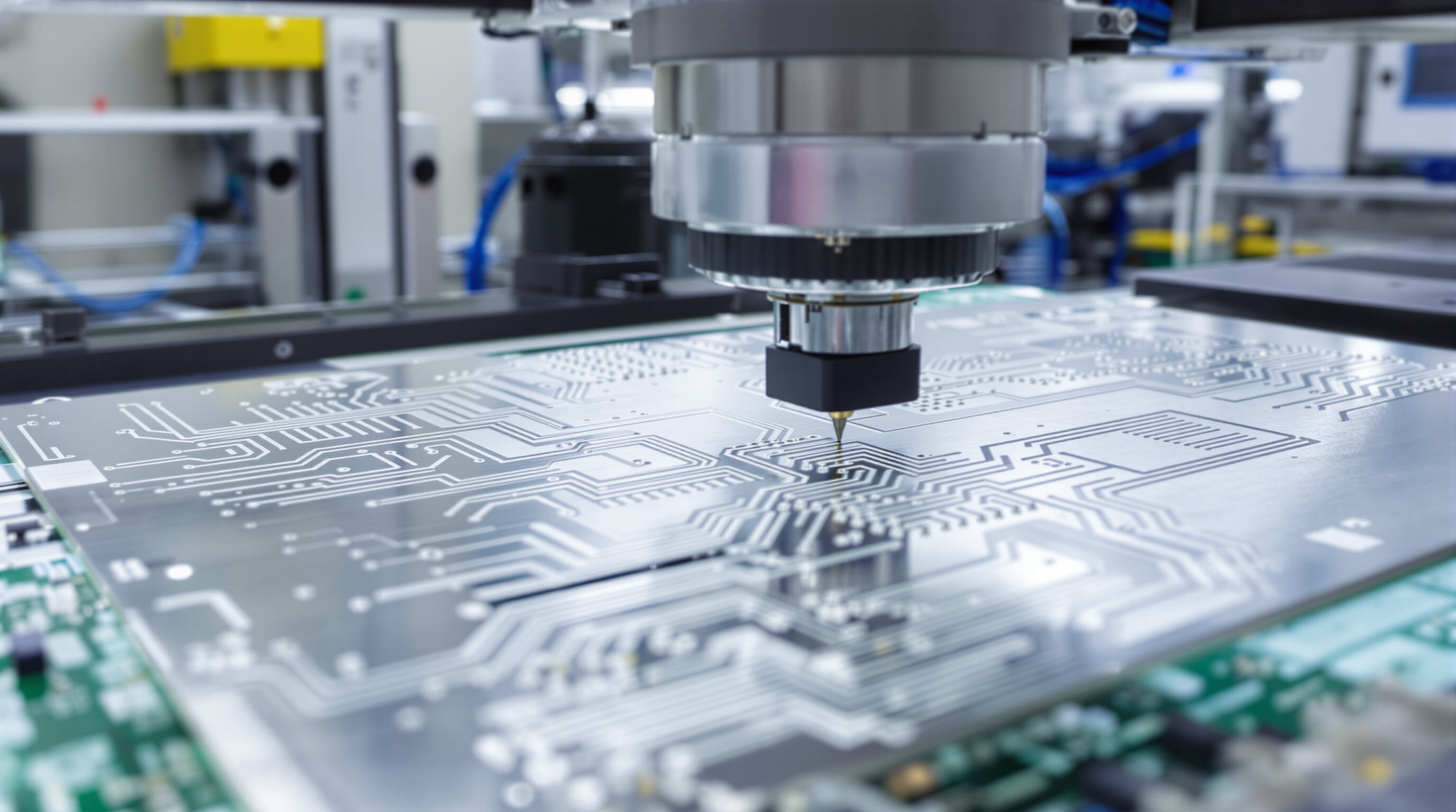
Selecting the Right SMT Placement Machine for Precision and Throughput Needs
Today's surface mount technology lines need placement equipment that can handle everything from those tiny 01005 chips measuring just 0.4 by 0.2 millimeters all the way up to bigger QFN packages. According to some research published last year, the best high speed chip shooters manage around plus or minus 0.025 mm accuracy even when running at over 35 thousand components per hour, which is really important stuff for making printed circuit boards used in cars. The newer modular setups with two lanes side by side let manufacturers work on different product mixes at once. This cuts down on how long it takes to switch between jobs by about two thirds when compared with older single lane systems, saving both time and money in the long run.
Feeder Systems and Vision Alignment: Key to Placement Accuracy
Advanced tape feeders with closed-loop tension monitoring prevent component mispick incidents, which account for 23% of placement errors in high-mix environments (IPC-9850 2022). Integrated 15-megapixel vision systems compensate for PCB warpage and reel alignment deviations in real time, achieving first-pass placement accuracies exceeding 99.92% on 0.4 mm pitch components.
Data-Driven Optimization of Placement Efficiency and Error Reduction
Machine learning algorithms analyze nozzle performance data to predict maintenance needs 72 hours before failure events. These systems reduce placement head downtime by 41% and ceramic capacitor waste by $18.6k annually per line (MFG Analytics 2024). Statistical process control dashboards flag anomalous placement force measurements beyond ±0.15N tolerance thresholds.
Balancing Speed and Precision in High-Density PCB Assembly
Top-tier manufacturers achieve sub-35 μm 3 ӑ placement repeatability on 0.3mm micro-BGA packages while maintaining 90% machine utilization rates. Dynamic thermal compensation systems counteract metal frame expansion during continuous operation, maintaining positional accuracy within ±8 μm despite 10°C ambient temperature fluctuations.
Mastering Reflow Soldering: Profiles, Thermal Control, and Quality Assurance
Developing Reliable Reflow Soldering Profiles and Oven Calibration
Creating precise thermal profiles is critical for solder joint integrity and component reliability. A well-designed profile follows four key stages:
| Zone | Temperature Range | Key Function |
|---|---|---|
| Preheat | 25–150°C | Gradual heating to prevent thermal shock |
| Soak | 150–180°C | Flux activation and oxide removal (60–120s) |
| Reflow | 220–250°C | Solder melting (30–60s above liquidus) |
| Cooling | Controlled descent | Rapid solidification for reliable joints |
Calibration involves matching oven settings to the solder paste manufacturer’s specifications, adjusting conveyor speed, and validating heat distribution using thermocouples. Maintaining a ramp-up rate of 1–3°C/s in preheating minimizes paste splatter and warping.
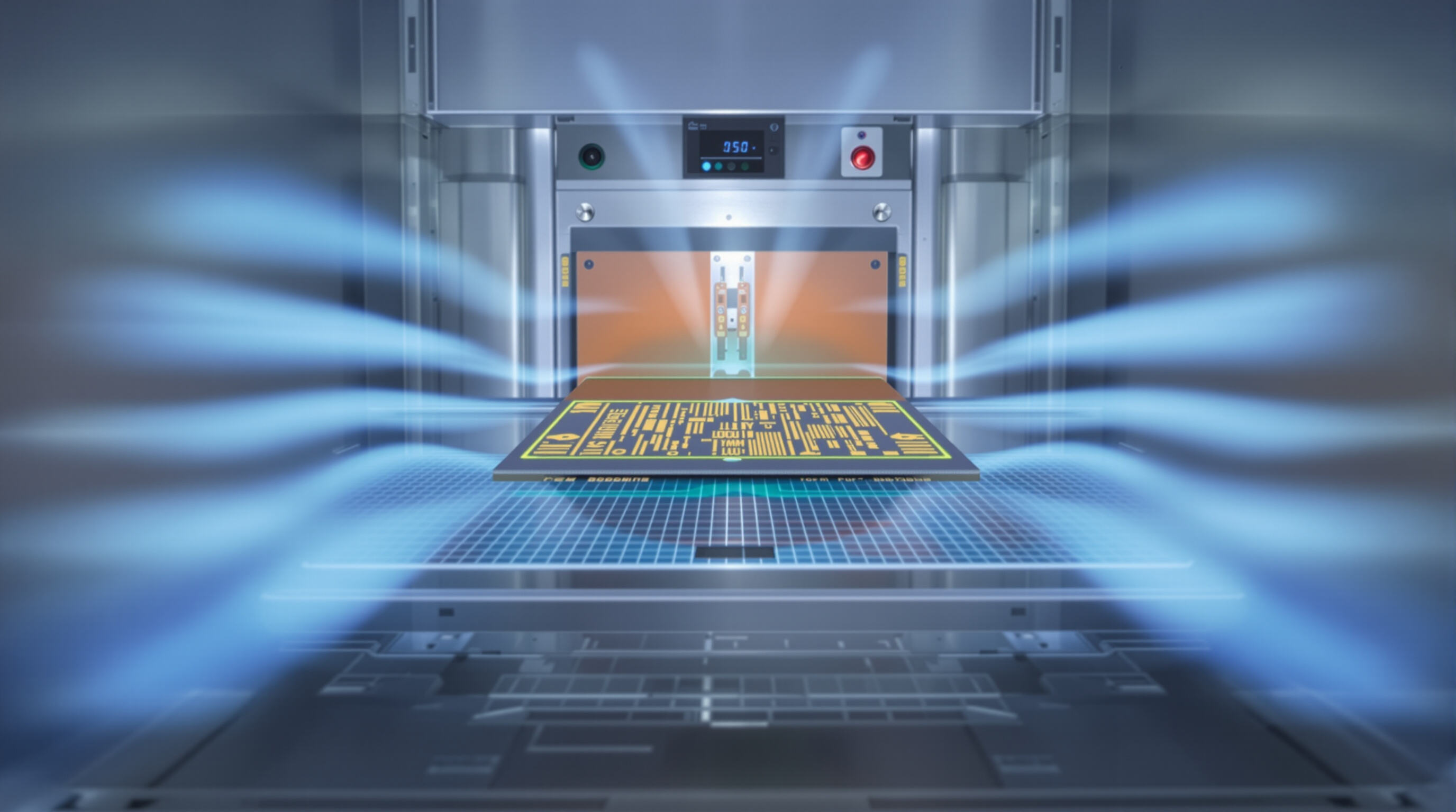
Ensuring Thermal Uniformity and Zoning Control in Advanced Reflow Ovens
Today's modern ovens typically feature between seven to twelve separate heating zones, each with its own temperature control settings. This setup helps handle different sized printed circuit boards and their various layout configurations. Getting good thermal uniformity across the board is really important, and manufacturers achieve this mainly through smart airflow management and adjusting those heating zones as needed. Without proper heat distribution, problems such as cold solder joints or components standing upright (what we call tombstoning) become much more common. When dealing with densely packed boards, many engineers actually slow down the conveyor belt by around ten to fifteen percent. This gives components more time in the crucial heating areas without completely sacrificing production speed, which remains a key concern for most manufacturing operations.
Closed-Loop Quality Monitoring Using Post-Reflow AOI and Thermal Sensors
When AOI systems get paired with thermal sensors, they create this amazing real time defect detection capability. These setups spot problems during manufacturing that might otherwise go unnoticed, things like those pesky solder bridges or when components don't wet properly on the board. The numbers speak for themselves too - after reflow operations, these inspection methods grab around 93 percent of all process related defects before they become bigger headaches later on. That translates to about a 40% drop in rework expenses according to industry reports. And let's not forget about thermal profiling tools either. They monitor those critical temperature peaks within plus or minus 5 degrees Celsius range, which is pretty tight control. This helps manufacturers stay compliant with important specs like IPC-J-STD-020 without constantly second guessing their processes.
By aligning these strategies, manufacturers achieve repeatable solder joint quality while supporting the scalability demands of modern SMT lines.
FAQ
What are SMT lines?
Surface Mount Technology (SMT) lines are manufacturing setups used to assemble electronic components onto printed circuit boards (PCBs) using automated equipment.
How do modular SMT setups benefit manufacturers?
Modular SMT setups allow manufacturers to switch printer placement modules in a short period, making them agile for product changes and reducing costs associated with machinery and production.
Why is alignment important in solder paste printing?
Proper alignment is crucial because misalignment exceeding 25 micron increases defect risk significantly, especially in high-density designs. Precision applications ensure better quality outcomes.
How do manufacturers ensure solder joint quality during reflow soldering?
Manufacturers use precise thermal profiles, multi-zone ovens, and real-time post-reflow AOI systems to monitor and ensure solder joint quality, reducing defects and rework costs.
Table of Contents
-
Understanding SMT Line Configuration and Core Integration Principles
- The Growing Complexity of SMT Line Setup in Modern Electronics Manufacturing
- Core Requirements for Seamless Integration of SMT Printers, Placement Machines, and Reflow Ovens
- Modular SMT Line Design: A Scalable Strategy for High-Mix Production Environments
- Aligning SMT Equipment with Production Goals: Throughput, Flexibility, and Yield
- Optimizing the Solder Paste Printing Process for Consistent SMT Quality
- Achieving High Accuracy in Component Placement with Pick and Place Machines
- Mastering Reflow Soldering: Profiles, Thermal Control, and Quality Assurance
- FAQ